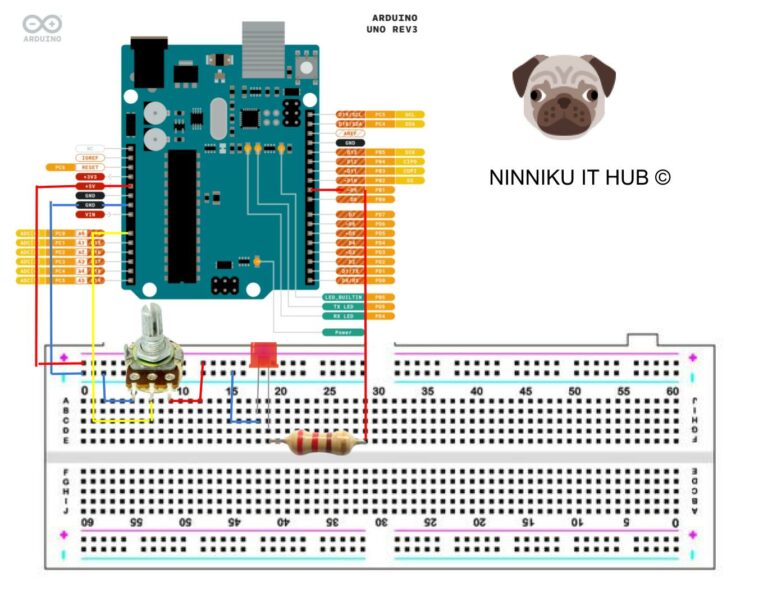
-
Shine Bright with Potentiometer: Controlling LED Brightness with PWM on Arduino
Introduction: Potentiometers are versatile devices commonly used in electronics to control the voltage or current of a circuit. In this article, we will explore how to use a potentiometer to control the brightness of an LED using pulse width modulation (PWM) on an Arduino board. By the end of this tutorial, you will be able to adjust the brightness of an LED using a simple potentiometer. Materials: Instructions: Conclusion: Controlling the brightness of an LED using a potentiometer and PWM on an Arduino board is a simple yet effective way to introduce yourself to the world of electronics. By understanding the principles behind PWM and how to use a potentiometer,…
-
Pulse-Width Modulation: The Art of Tickling Your Electronics
Have you ever wondered how your electric toothbrush or the motor in your drone works? Chances are, they use a technique called Pulse Width Modulation (PWM). PWM is a clever way of controlling the amount of power delivered to a load by rapidly switching it on and off. This technique has a wide range of applications, from simple LED dimming to more complex motor control. In this article, we’ll dive deep into the world of PWM and explore its inner workings, applications, and how you can implement it in your own projects. So, fasten your seatbelts, and let’s get started! Image Source:https://www.digikey.tw/ In this article, we will explore pulse width…
-
Arduino Tutorial: Control LED Brightness with PWM for Breathing Effect
In the previous Arduino tutorial, we learned how to control the on/off state of an LED. In this tutorial, we will learn how to control the brightness of an LED using Pulse Width Modulation (PWM) with Arduino. https://www.ninniku.tw/getting-started-with-arduino-lighting-up-an-led/ The LED brightness is controlled by adjusting the duty cycle of the PWM signal. The duty cycle is the ratio of the time the signal is on to the total time of one cycle. The larger the duty cycle, the brighter the LED, and vice versa. Step 1: Connect the Circuit We will keep Pin 8 as a digital control circuit, and connect it to the red LED on the circuit. Another…