Learn how to light up LEDs with an Arduino Uno board and the proper wiring techniques. Discover the voltage requirements for different colored LEDs and how to calculate the necessary resistor value using Ohm’s law. Follow the step-by-step instructions and see how easy it is to connect and control your own red and blue LEDs with an Arduino Uno board.
The Arduino Uno development board provides only 5V or 3.3V of electricity, which is generally too high. To avoid burning out the LED, we must add a resistor.
First of all, you need to understand Ohm’s law and resistor color codes.
Ohm’s Law: The current flowing through a circuit is proportional to the voltage applied and inversely proportional to the resistance in the circuit.
Ohm’s Law formula:
V = IR, voltage = current x resistance
V = voltage in volts I = current in amperes R = resistance in ohms
To calculate the required resistance value, the formula becomes:
R = V / I, resistance = voltage / current
LED Current
The typical current value for a red LED is around 20mA, and for a blue LED, it is also around 20mA. However, the actual current value may vary depending on the specific LED and circuit configuration. It’s important to check the datasheet or specifications for the LED to determine the appropriate current rating for your circuit.
LED Voltage
Red LED: 2.1-2.6V
Blue LED: 3.2-4.0V
Prepare Resistor
RED LED resistor:
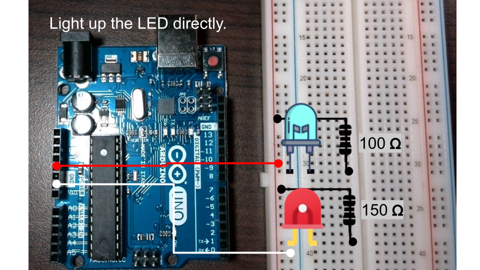
R = V / I = (5-2) / 0.02 = 150
You can learn how to identify resistor color codes in the following article.
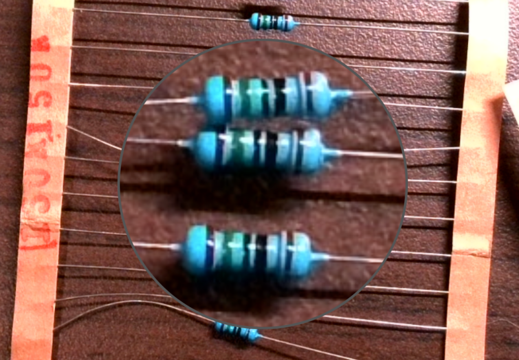
brown green black
Image source: Ninniku IT HUB
Blue LED resistor:
R = V / I = (5-3) / 0.02 = 100
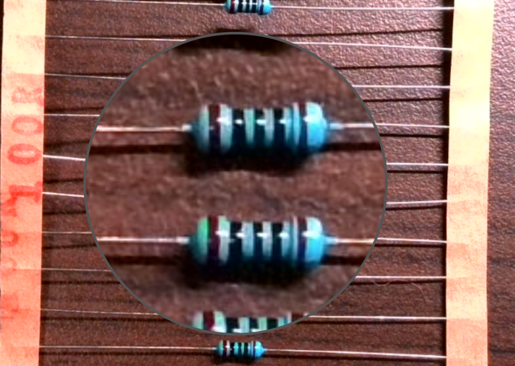
brown black black
Image source: Ninniku IT HUB
Light up the LED directly.
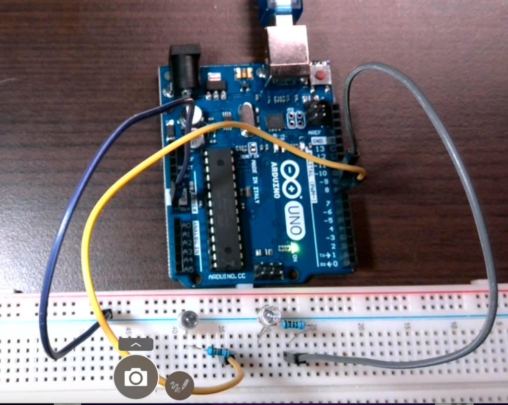
Directly wire from the 5V power supply, the voltage is lowered by the resistor and then supplied to the LED. Finally, connect to the ground to complete the circuit.
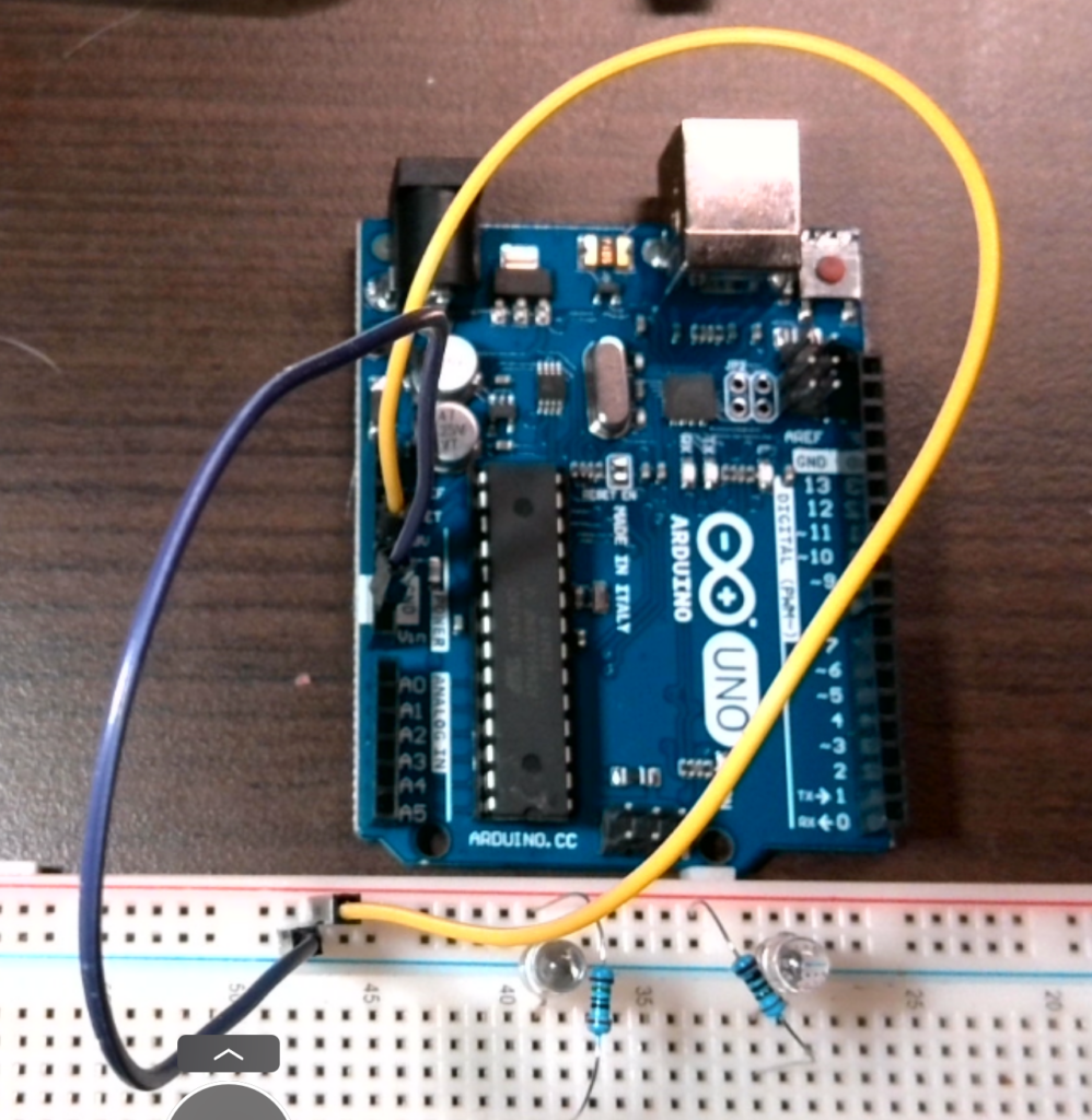
I have connected all the wires.
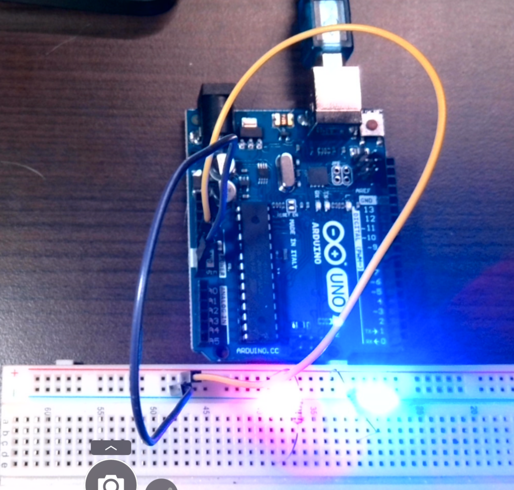
After plugging in the USB cable, they should light up, barring any unexpected issues.
Next, we will use the digital pins to control the on/off state of the Red LED and Blue LED respectively.
We’ll rewire the circuit. Remove the 5V power wire. Change to connect Pin 8 to the RED LED and Pin 9 to the Blue LED.
Open your Arduino IDE. We will use the Blink example program as a template. Click on “File > Examples > Basics > Blink” in the main menu.
In the setup() function, let’s initialize digital pin 8 and pin 9 as outputs.
// the setup function runs once when you press reset or power the board
void setup() {
  // initialize digital pin LED_BUILTIN as an output.
  pinMode(8, OUTPUT);
  pinMode(9, OUTPUT);

}
In the loop() function, replace LED_BUILTIN with 8. Then, copy the code and paste it for the blue LED, and replace it with 9.
// the loop function runs over and over again forever
void loop() {
  //red led
  digitalWrite(8, HIGH);  // turn the LED on (HIGH is the voltage level)
  delay(1000);                      // wait for a second
  digitalWrite(8, LOW);   // turn the LED off by making the voltage LOW
  delay(1000);
  //blue led                   // wait for a second
  digitalWrite(9, HIGH);  // turn the LED on (HIGH is the voltage level)
  delay(1000);                      // wait for a second
  digitalWrite(9, LOW);   // turn the LED off by making the voltage LOW
  delay(1000);

}
Let’s plug in the power and see the results!
In conclusion
In this practice, we learned how to control multiple LEDs using an Arduino board. We started by understanding Ohm’s law and resistor color codes and then proceeded to connect the LEDs to the Arduino board through resistors. We also learned how to write code in the Arduino Integrated Development Environment (IDE) to control the LEDs through digital pins.
Through this practice, we gained valuable knowledge on the basics of electronics and programming, and we were able to apply that knowledge to create a simple circuit and program that controlled multiple LEDs. This is just the beginning of what we can do with the Arduino board, and we can continue to explore and expand our knowledge to create more complex projects.
Next, you may want to learn how to control analog output through PWM.
English Version
Learn how to light up LEDs with an Arduino Uno board and the proper wiring techniques. Discover the voltage requirements for different colored LEDs and how to calculate the necessary resistor value using Ohm’s law. Follow the step-by-step instructions and see how easy it is to connect and control your own red and blue LEDs with an Arduino Uno board.
The Arduino Uno development board provides only 5V or 3.3V of electricity, which is generally too high. To avoid burning out the LED, we must add a resistor.
First of all, you need to understand Ohm’s law and resistor color codes.
Ohm’s Law: The current flowing through a circuit is proportional to the voltage applied and inversely proportional to the resistance in the circuit.
Ohm’s Law formula:
V = IR, voltage = current x resistance
V = voltage in volts I = current in amperes R = resistance in ohms
To calculate the required resistance value, the formula becomes:
R = V / I, resistance = voltage / current
LED Current
The typical current value for a red LED is around 20mA, and for a blue LED, it is also around 20mA. However, the actual current value may vary depending on the specific LED and circuit configuration. It’s important to check the datasheet or specifications for the LED to determine the appropriate current rating for your circuit.
LED Voltage
Red LED: 2.1-2.6V
Blue LED: 3.2-4.0V
Prepare Resistor
RED LED resistor:
R = V / I = (5-2) / 0.02 = 150
You can learn how to identify resistor color codes in the following article.
brown green black
Image source: Ninniku IT HUB
Blue LED resistor:
R = V / I = (5-3) / 0.02 = 100
brown black black
Image source: Ninniku IT HUB
Light up the LED directly.
Directly wire from the 5V power supply, the voltage is lowered by the resistor and then supplied to the LED. Finally, connect to the ground to complete the circuit.
I have connected all the wires.
After plugging in the USB cable, they should light up, barring any unexpected issues.
Next, we will use the digital pins to control the on/off state of the Red LED and Blue LED respectively.
We’ll rewire the circuit. Remove the 5V power wire. Change to connect Pin 8 to the RED LED and Pin 9 to the Blue LED.
Open your Arduino IDE. We will use the Blink example program as a template. Click on “File > Examples > Basics > Blink” in the main menu.
In the setup() function, let’s initialize digital pin 8 and pin 9 as outputs.
// the setup function runs once when you press reset or power the board
void setup() {
  // initialize digital pin LED_BUILTIN as an output.
  pinMode(8, OUTPUT);
  pinMode(9, OUTPUT);

}
In the loop() function, replace LED_BUILTIN with 8. Then, copy the code and paste it for the blue LED, and replace it with 9.
// the loop function runs over and over again forever
void loop() {
  //red led
  digitalWrite(8, HIGH);  // turn the LED on (HIGH is the voltage level)
  delay(1000);                      // wait for a second
  digitalWrite(8, LOW);   // turn the LED off by making the voltage LOW
  delay(1000);
  //blue led                   // wait for a second
  digitalWrite(9, HIGH);  // turn the LED on (HIGH is the voltage level)
  delay(1000);                      // wait for a second
  digitalWrite(9, LOW);   // turn the LED off by making the voltage LOW
  delay(1000);

}
Let’s plug in the power and see the results!
In conclusion
In this practice, we learned how to control multiple LEDs using an Arduino board. We started by understanding Ohm’s law and resistor color codes and then proceeded to connect the LEDs to the Arduino board through resistors. We also learned how to write code in the Arduino Integrated Development Environment (IDE) to control the LEDs through digital pins.
Through this practice, we gained valuable knowledge on the basics of electronics and programming, and we were able to apply that knowledge to create a simple circuit and program that controlled multiple LEDs. This is just the beginning of what we can do with the Arduino board, and we can continue to explore and expand our knowledge to create more complex projects.
Next, you may want to learn how to control analog output through PWM.
日本語版
Arduino Unoボードを使ったLEDの点灯方法と正しい配線テクニックを学びましょう。異なる色のLEDの電圧要件と、オームの法則を使って必要な抵抗値を計算する方法を発見できます。ステップバイステップの手順に従って、Arduino Unoボードで赤色LEDと青色LEDを接続・制御する方法を確認しましょう。
Arduino Uno開発ボードは5Vまたは3.3Vの電圧しか供給しませんが、一般的にこれは高すぎます。LEDの焼損を防ぐために、抵抗を追加する必要があります。
まず、オームの法則と抵抗のカラーコードを理解する必要があります。
オームの法則:回路を流れる電流は、印加された電圧に比例し、回路の抵抗に反比例します。
オームの法則の公式:
V = IR、電圧 = 電流 x 抵抗
V = 電圧(ボルト) I = 電流(アンペア) R = 抵抗(オーム)
必要な抵抗値を計算するには、公式は次のようになります:
R = V / I、抵抗 = 電圧 / 電流
LEDの電流
赤色LEDの一般的な電流値は約20mAで、青色LEDも約20mAです。ただし、実際の電流値は、特定のLEDや回路構成によって異なる場合があります。回路に適切な電流定格を決定するために、LEDのデータシートや仕様書を確認することが重要です。
LEDの電圧
赤色LED:2.1-2.6V
青色LED:3.2-4.0V
抵抗の準備
赤色LED用抵抗:
R = V / I = (5-2) / 0.02 = 150
以下の記事で抵抗のカラーコードの識別方法を学ぶことができます。
茶 緑 黒
画像出典:Ninniku IT HUB
青色LED用抵抗:
R = V / I = (5-3) / 0.02 = 100
茶 黒 黒
画像出典:Ninniku IT HUB
LEDを直接点灯させる
5V電源から直接配線し、抵抗で電圧を下げてからLEDに供給します。最後にグランドに接続して回路を完成させます。
すべてのワイヤーを接続しました。
USBケーブルを差し込むと、予期しない問題がなければ点灯するはずです。
次に、デジタルピンを使って赤色LEDと青色LEDのオン・オフをそれぞれ制御します。
回路を再配線します。5V電源ワイヤーを取り外します。ピン8を赤色LEDに、ピン9を青色LEDに接続するように変更します。
Arduino IDEを開きます。Blinkのサンプルプログラムをテンプレートとして使用します。メインメニューで「File > Examples > Basics > Blink」をクリックします。
setup()関数で、デジタルピン8とピン9を出力として初期化しましょう。
// the setup function runs once when you press reset or power the board
void setup() {
  // initialize digital pin LED_BUILTIN as an output.
  pinMode(8, OUTPUT);
  pinMode(9, OUTPUT);

}
loop()関数で、LED_BUILTINを8に置き換えます。次に、コードをコピーして青色LED用に貼り付け、9に置き換えます。
// the loop function runs over and over again forever
void loop() {
  //red led
  digitalWrite(8, HIGH);  // turn the LED on (HIGH is the voltage level)
  delay(1000);                      // wait for a second
  digitalWrite(8, LOW);   // turn the LED off by making the voltage LOW
  delay(1000);
  //blue led                   // wait for a second
  digitalWrite(9, HIGH);  // turn the LED on (HIGH is the voltage level)
  delay(1000);                      // wait for a second
  digitalWrite(9, LOW);   // turn the LED off by making the voltage LOW
  delay(1000);

}
電源を差し込んで結果を見てみましょう!
まとめ
この実践では、Arduinoボードを使用して複数のLEDを制御する方法を学びました。オームの法則と抵抗のカラーコードを理解することから始め、抵抗を通じてLEDをArduinoボードに接続する方法に進みました。また、Arduino統合開発環境(IDE)でコードを書き、デジタルピンを通じてLEDを制御する方法も学びました。
この実践を通じて、電子工学とプログラミングの基礎に関する貴重な知識を得ることができ、その知識を活用して複数のLEDを制御するシンプルな回路とプログラムを作成することができました。これはArduinoボードでできることの始まりに過ぎず、知識を探求・拡大し続けて、より複雑なプロジェクトを作成することができます。