Excerpt
In this article, you will learn how to use an Arduino board and a button to control an LED. The article provides a step-by-step guide to setting up the circuit and programming the board using the Arduino IDE. The code example demonstrates how to turn on the LED when the button is pressed and turn…
Description
In this course, you will learn how to use a button to control an LED on an Arduino board. You will start by understanding the basic concepts of Arduino programming and circuitry, and then move on to learning how to set up the circuit and write the code to turn the LED on and off using the button. You will also learn how to use conditional statements and functions to create more complex behaviors for your LED. By the end of this course, you will have a solid understanding of how to use buttons to control LEDs on your Arduino, and you’ll be ready to create your own interactive projects! Get ready to unleash your inner inventor and join us on this fun and engaging Arduino adventure!
To complete the project of using a button to switch an LED on and off on an Arduino, the following components and tools will be required:
- Arduino board (e.g., Arduino Uno)
- Breadboard
- LED (any color)
- 220 Ohm resistor
- Push button switch
- Jumper wires
- USB cable (Type A to Type B)
These components can typically be found in most electronics starter kits, and can also be purchased individually online or at electronics stores. It’s important to make sure that the LED, resistor, and push button switch are all rated for use with the Arduino’s voltage and current limits. Additionally, a computer with the Arduino IDE (Integrated Development Environment) installed will be needed to write and upload the code to the Arduino board.
Setting up the Circuit
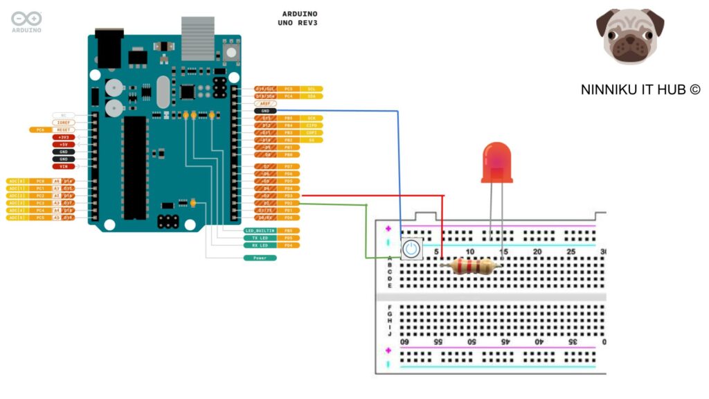
To set up the circuit for controlling an LED using a button with Arduino, follow these steps:
- Gather the required components and tools, as listed in the previous section.
- Connect one end of the resistor to the long leg of the LED. The resistor should have a value of around 220 ohms.
- Connect the other end of the resistor to an empty row on the breadboard.
- Connect the short leg of the LED to the negative rail on the breadboard.
- Connect one leg of the button to an empty row on the breadboard.
- Connect the other leg of the button to the negative rail on the breadboard.
- Connect a wire from the row with the button to digital pin 2 on the Arduino.
- Connect a wire from the row with the LED to digital pin 3 on the Arduino.
- Finally, connect the Arduino to your computer using a USB cable.
The circuit is now set up and ready to be programmed.
Preventing Floating State
When using digital pins as inputs in Arduino, it is easy to encounter a floating state. Normally, a resistor pull-up or pull-down is used to solve this problem. In this example, we use the built-in resistor pull-up in Arduino to simplify the circuit complexity.
If you want to understand what Pull-up and Pull-down are, you can refer to the following article.
Programming the Arduino Board
Now that the circuit is set up, it’s time to write the code that will control the LED and read the button input. The Arduino programming language is based on C++, and the Arduino IDE provides a simplified programming environment with built-in functions and libraries that can be used to interact with the board’s hardware.
Here’s an example code that will turn on the LED when the button is pressed, and turn it off when the button is released:
// Pin assignments
const int buttonPin = 2;
const int ledPin = 3;

// Variables
int buttonState = 0;

void setup() {
  pinMode(buttonPin, INPUT_PULLUP);
  pinMode(ledPin, OUTPUT);
  Serial.begin(9600);
}

void loop() {
  // Read the state of the button
  buttonState = digitalRead(buttonPin);
  Serial.print("buttonPin value: ");  // Print potentiometer value
  Serial.print(buttonPin);
  Serial.print(" Status: ");
  Serial.println (buttonState);

  // If the button is pressed, turn on the LED
  if (buttonState == LOW) {
    digitalWrite(ledPin, HIGH);
  }
  // Otherwise, turn off the LED
  else {
    digitalWrite(ledPin, LOW);
  }
}
The code starts by defining the pin numbers for the button and LED using const int variables. In the setup() function, we set the button pin as an input (pull-up) and the LED pin as an output using the pinMode() function.
In the loop() function, we read the state of the button using digitalRead() and store it in the buttonState variable. If the button is pressed (buttonState is HIGH), we turn on the LED using digitalWrite(). Otherwise, we turn off the LED by setting the LED pin to LOW.
You can customize this code to change the pin assignments or add more functionality, such as changing the LED brightness based on how long the button is pressed. Once you’re done editing the code, you can upload it to the Arduino board by clicking the “Upload” button in the IDE. The code will be compiled and transferred to the board’s microcontroller, and the LED and button should start responding to the button presses.
Customizing and Expanding the Circuit
Once you have successfully programmed the Arduino board to control the LED using a button, you can start customizing and expanding the circuit. Here are some ideas to get you started:
- Add more LEDs: You can add multiple LEDs to the circuit and control them with different buttons. This can create more complex lighting effects.
- Use different types of buttons: Experiment with different types of buttons, such as push buttons, toggle switches, or capacitive touch sensors. Each type of button will require different wiring and programming.
- Integrate with other sensors: You can add other sensors to the circuit, such as light sensors or motion sensors, to create a more interactive and responsive system.
- Connect to the internet: If you have an internet-connected Arduino board, you can control the LED and button remotely using a smartphone or computer.
- Build a custom enclosure: Once you have finalized your circuit, you can build a custom enclosure to house the Arduino board, the LED, and the button. This will give your project a more polished and professional look.
Remember, the possibilities are endless when it comes to customizing and expanding your Arduino circuit. Don’t be afraid to experiment and try new things.
Conclusion
In conclusion, building a button-controlled LED circuit on an Arduino board is a fun and educational project that can be completed by beginners and advanced hobbyists alike. With a few basic components and tools, anyone can create a working circuit and customize it to their liking. By following the steps outlined in this guide, you can learn the basics of electronics and programming while creating a fun and interactive project. So go ahead and try it out, and see what other cool things you can create with your Arduino board!
English Version
Excerpt
In this article, you will learn how to use an Arduino board and a button to control an LED. The article provides a step-by-step guide to setting up the circuit and programming the board using the Arduino IDE. The code example demonstrates how to turn on the LED when the button is pressed and turn…
Description
In this course, you will learn how to use a button to control an LED on an Arduino board. You will start by understanding the basic concepts of Arduino programming and circuitry, and then move on to learning how to set up the circuit and write the code to turn the LED on and off using the button. You will also learn how to use conditional statements and functions to create more complex behaviors for your LED. By the end of this course, you will have a solid understanding of how to use buttons to control LEDs on your Arduino, and you’ll be ready to create your own interactive projects! Get ready to unleash your inner inventor and join us on this fun and engaging Arduino adventure!
To complete the project of using a button to switch an LED on and off on an Arduino, the following components and tools will be required:
- Arduino board (e.g., Arduino Uno)
- Breadboard
- LED (any color)
- 220 Ohm resistor
- Push button switch
- Jumper wires
- USB cable (Type A to Type B)
These components can typically be found in most electronics starter kits, and can also be purchased individually online or at electronics stores. It’s important to make sure that the LED, resistor, and push button switch are all rated for use with the Arduino’s voltage and current limits. Additionally, a computer with the Arduino IDE (Integrated Development Environment) installed will be needed to write and upload the code to the Arduino board.
Setting up the Circuit
To set up the circuit for controlling an LED using a button with Arduino, follow these steps:
- Gather the required components and tools, as listed in the previous section.
- Connect one end of the resistor to the long leg of the LED. The resistor should have a value of around 220 ohms.
- Connect the other end of the resistor to an empty row on the breadboard.
- Connect the short leg of the LED to the negative rail on the breadboard.
- Connect one leg of the button to an empty row on the breadboard.
- Connect the other leg of the button to the negative rail on the breadboard.
- Connect a wire from the row with the button to digital pin 2 on the Arduino.
- Connect a wire from the row with the LED to digital pin 3 on the Arduino.
- Finally, connect the Arduino to your computer using a USB cable.
The circuit is now set up and ready to be programmed.
Preventing Floating State
When using digital pins as inputs in Arduino, it is easy to encounter a floating state. Normally, a resistor pull-up or pull-down is used to solve this problem. In this example, we use the built-in resistor pull-up in Arduino to simplify the circuit complexity.
If you want to understand what Pull-up and Pull-down are, you can refer to the following article.
Programming the Arduino Board
Now that the circuit is set up, it’s time to write the code that will control the LED and read the button input. The Arduino programming language is based on C++, and the Arduino IDE provides a simplified programming environment with built-in functions and libraries that can be used to interact with the board’s hardware.
Here’s an example code that will turn on the LED when the button is pressed, and turn it off when the button is released:
// Pin assignments
const int buttonPin = 2;
const int ledPin = 3;

// Variables
int buttonState = 0;

void setup() {
  pinMode(buttonPin, INPUT_PULLUP);
  pinMode(ledPin, OUTPUT);
  Serial.begin(9600);
}

void loop() {
  // Read the state of the button
  buttonState = digitalRead(buttonPin);
  Serial.print("buttonPin value: ");  // Print potentiometer value
  Serial.print(buttonPin);
  Serial.print(" Status: ");
  Serial.println (buttonState);

  // If the button is pressed, turn on the LED
  if (buttonState == LOW) {
    digitalWrite(ledPin, HIGH);
  }
  // Otherwise, turn off the LED
  else {
    digitalWrite(ledPin, LOW);
  }
}
The code starts by defining the pin numbers for the button and LED using const int variables. In the setup() function, we set the button pin as an input (pull-up) and the LED pin as an output using the pinMode() function.
In the loop() function, we read the state of the button using digitalRead() and store it in the buttonState variable. If the button is pressed (buttonState is HIGH), we turn on the LED using digitalWrite(). Otherwise, we turn off the LED by setting the LED pin to LOW.
You can customize this code to change the pin assignments or add more functionality, such as changing the LED brightness based on how long the button is pressed. Once you’re done editing the code, you can upload it to the Arduino board by clicking the “Upload” button in the IDE. The code will be compiled and transferred to the board’s microcontroller, and the LED and button should start responding to the button presses.
Customizing and Expanding the Circuit
Once you have successfully programmed the Arduino board to control the LED using a button, you can start customizing and expanding the circuit. Here are some ideas to get you started:
- Add more LEDs: You can add multiple LEDs to the circuit and control them with different buttons. This can create more complex lighting effects.
- Use different types of buttons: Experiment with different types of buttons, such as push buttons, toggle switches, or capacitive touch sensors. Each type of button will require different wiring and programming.
- Integrate with other sensors: You can add other sensors to the circuit, such as light sensors or motion sensors, to create a more interactive and responsive system.
- Connect to the internet: If you have an internet-connected Arduino board, you can control the LED and button remotely using a smartphone or computer.
- Build a custom enclosure: Once you have finalized your circuit, you can build a custom enclosure to house the Arduino board, the LED, and the button. This will give your project a more polished and professional look.
Remember, the possibilities are endless when it comes to customizing and expanding your Arduino circuit. Don’t be afraid to experiment and try new things.
Conclusion
In conclusion, building a button-controlled LED circuit on an Arduino board is a fun and educational project that can be completed by beginners and advanced hobbyists alike. With a few basic components and tools, anyone can create a working circuit and customize it to their liking. By following the steps outlined in this guide, you can learn the basics of electronics and programming while creating a fun and interactive project. So go ahead and try it out, and see what other cool things you can create with your Arduino board!
日本語版
抜粋
In this article, you will learn how to use an Arduino board and a button to control an LED. The article provides a step-by-step guide to setting up the circuit and programming the board using the Arduino IDE. The code example demonstrates how to turn on the LED when the button is pressed and turn…
説明
このコースでは、Arduinoボード上のLEDをボタンで制御する方法を学びます。Arduinoプログラミングと回路の基本概念を理解することから始め、次にボタンを使用してLEDのオン・オフを切り替える回路のセットアップとコードの書き方を学びます。また、条件文や関数を使用して、LEDのより複雑な動作を作成する方法も学びます。このコースの終了時には、Arduinoでボタンを使ってLEDを制御する方法をしっかりと理解し、自分だけのインタラクティブなプロジェクトを作成する準備が整います!内なる発明家を解き放ち、この楽しくて魅力的なArduinoの冒険に参加しましょう!
ArduinoでボタンによるLEDのオン・オフ切り替えプロジェクトを完成させるには、以下のコンポーネントとツールが必要です:
- Arduinoボード(例:Arduino Uno)
- ブレッドボード
- LED(任意の色)
- 220オーム抵抗器
- プッシュボタンスイッチ
- ジャンパーワイヤー
- USBケーブル(Type AからType B)
これらのコンポーネントは、ほとんどの電子工作スターターキットに含まれており、オンラインまたは電子部品店で個別に購入することもできます。LED、抵抗器、プッシュボタンスイッチがすべてArduinoの電圧および電流制限内で使用できる定格であることを確認することが重要です。さらに、Arduino IDE(統合開発環境)がインストールされたコンピュータが、コードの作成とArduinoボードへのアップロードに必要です。
回路のセットアップ
Arduinoでボタンを使ってLEDを制御するための回路をセットアップするには、以下の手順に従ってください:
- 前のセクションにリストされている必要なコンポーネントとツールを集めてください。
- 抵抗器の一端をLEDの長い脚に接続します。抵抗器の値は約220オームです。
- 抵抗器のもう一端をブレッドボードの空いている行に接続します。
- LEDの短い脚をブレッドボードのマイナスレールに接続します。
- ボタンの一方の脚をブレッドボードの空いている行に接続します。
- ボタンのもう一方の脚をブレッドボードのマイナスレールに接続します。
- ボタンがある行からArduinoのデジタルピン2にワイヤーを接続します。
- LEDがある行からArduinoのデジタルピン3にワイヤーを接続します。
- 最後に、USBケーブルを使用してArduinoをコンピュータに接続します。
これで回路のセットアップが完了し、プログラミングの準備が整いました。
フローティング状態の防止
Arduinoでデジタルピンを入力として使用する場合、フローティング状態に遭遇しやすくなります。通常、この問題を解決するためにプルアップ抵抗またはプルダウン抵抗が使用されます。この例では、回路の複雑さを簡素化するためにArduinoの内蔵プルアップ抵抗を使用します。
プルアップとプルダウンとは何かを理解したい場合は、以下の記事を参照してください。
Arduinoボードのプログラミング
回路のセットアップが完了したら、LEDを制御しボタン入力を読み取るコードを書く時です。Arduinoのプログラミング言語はC++をベースとしており、Arduino IDEはボードのハードウェアと対話するために使用できる組み込み関数やライブラリを備えた簡素化されたプログラミング環境を提供します。
以下は、ボタンが押されたときにLEDをオンにし、ボタンが離されたときにオフにするサンプルコードです:
// ピンの割り当て
const int buttonPin = 2;
const int ledPin = 3;

// 変数
int buttonState = 0;

void setup() {
  pinMode(buttonPin, INPUT_PULLUP);
  pinMode(ledPin, OUTPUT);
  Serial.begin(9600);
}

void loop() {
  // ボタンの状態を読み取る
  buttonState = digitalRead(buttonPin);
  Serial.print("buttonPin value: ");  // ポテンショメータの値を表示
  Serial.print(buttonPin);
  Serial.print(" Status: ");
  Serial.println (buttonState);

  // ボタンが押されたら、LEDをオンにする
  if (buttonState == LOW) {
    digitalWrite(ledPin, HIGH);
  }
  // それ以外の場合、LEDをオフにする
  else {
    digitalWrite(ledPin, LOW);
  }
}
コードはまず、const int変数を使用してボタンとLEDのピン番号を定義します。setup()関数では、pinMode()関数を使用して、ボタンピンを入力(プルアップ)として、LEDピンを出力として設定します。
loop()関数では、digitalRead()を使用してボタンの状態を読み取り、buttonState変数に格納します。ボタンが押されている場合(buttonStateがHIGH)、digitalWrite()を使用してLEDをオンにします。それ以外の場合は、LEDピンをLOWに設定してLEDをオフにします。
このコードをカスタマイズして、ピンの割り当てを変更したり、ボタンが押されている時間に基づいてLEDの明るさを変更するなどの機能を追加したりできます。コードの編集が完了したら、IDEの「アップロード」ボタンをクリックしてArduinoボードにアップロードできます。コードがコンパイルされてボードのマイクロコントローラに転送され、LEDとボタンがボタン操作に応答し始めます。
回路のカスタマイズと拡張
Arduinoボードのプログラミングに成功してボタンでLEDを制御できるようになったら、回路のカスタマイズと拡張を始めることができます。以下にいくつかのアイデアを紹介します:
- LEDを追加する:回路に複数のLEDを追加し、異なるボタンで制御できます。これにより、より複雑な照明効果を作成できます。
- 異なるタイプのボタンを使用する:プッシュボタン、トグルスイッチ、静電容量式タッチセンサーなど、さまざまなタイプのボタンを試してみてください。各タイプのボタンには異なる配線とプログラミングが必要です。
- 他のセンサーと統合する:光センサーやモーションセンサーなどの他のセンサーを回路に追加して、よりインタラクティブで応答性の高いシステムを作成できます。
- インターネットに接続する:インターネット接続可能なArduinoボードがあれば、スマートフォンやコンピュータを使用してLEDとボタンをリモートで制御できます。
- カスタムエンクロージャーを作る:回路が完成したら、Arduinoボード、LED、ボタンを収納するカスタムエンクロージャーを作成できます。これにより、プロジェクトがより洗練されたプロフェッショナルな外観になります。
Arduino回路のカスタマイズと拡張の可能性は無限大です。実験を恐れず、新しいことに挑戦してください。
結論
結論として、Arduinoボード上にボタン制御のLED回路を構築することは、初心者から上級者まで楽しめる教育的なプロジェクトです。いくつかの基本的なコンポーネントとツールがあれば、誰でも動作する回路を作成し、好みに合わせてカスタマイズできます。このガイドで説明した手順に従うことで、楽しくインタラクティブなプロジェクトを作成しながら、電子工作とプログラミングの基礎を学ぶことができます。ぜひ試してみて、Arduinoボードで他にどんなクールなものが作れるか確かめてください!