Have you ever wondered how your electric toothbrush or the motor in your drone works? Chances are, they use a technique called Pulse Width Modulation (PWM). PWM is a clever way of controlling the amount of power delivered to a load by rapidly switching it on and off. This technique has a wide range of applications, from simple LED dimming to more complex motor control. In this article, we’ll dive deep into the world of PWM and explore its inner workings, applications, and how you can implement it in your own projects. So, fasten your seatbelts, and let’s get started!

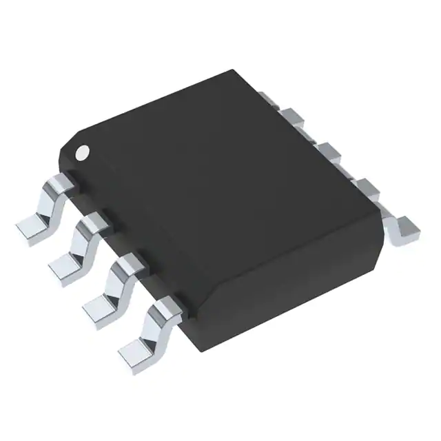
Image Source:https://www.digikey.tw/
In this article, we will explore pulse width modulation (PWM) in depth. PWM is a widely used technique for controlling the power delivered to electronic devices. It involves varying the duty cycle of a periodic signal to control the average power delivered to a load.
The first section will cover the basics of PWM, including how it works, its advantages, and its applications. We will then dive deeper into the theory behind PWM and discuss its mathematical representation, which involves calculating the pulse width, frequency, and duty cycle of the signal.
Next, we will explore different types of PWM, including single-ended PWM, push-pull PWM, and bridge PWM. Each type has its own advantages and disadvantages, and we will examine them in detail.
We will also discuss the implementation of PWM using microcontrollers and digital signal processors (DSPs). We will cover the hardware and software requirements, including the use of timers, counters, and interrupts. Additionally, we will provide sample code and circuit diagrams to help readers get started with PWM implementation.
Finally, we will discuss some advanced PWM techniques, including phase-shifted PWM, frequency modulation (FM) PWM, and space vector PWM. These techniques are used to improve the efficiency and performance of PWM-based systems and are commonly used in motor control applications.
By the end of this article, readers will have a comprehensive understanding of PWM and its applications. They will also be equipped with the knowledge and tools to implement PWM in their own projects and designs.
The principle of PWM: Pulse Width Modulation (PWM)
PWM is a technique widely used in electronics and engineering for controlling the amount of power delivered to a load, such as a motor or LED, by varying the duty cycle of a periodic waveform. In simple terms, PWM involves turning a signal on and off at a certain frequency and with a variable duty cycle, where the duty cycle represents the proportion of time that the signal is “on” during each cycle.
The advantages of using PWM are numerous, including increased efficiency, precise control, and reduced heat dissipation. PWM is widely used in various applications, such as motor control, LED dimming, audio signal generation, and power conversion.
In this article, we will explore the theory behind PWM, its applications, and how it can be implemented using different electronic components and microcontrollers. We’ll also delve into some common issues and techniques used to overcome them in PWM circuits.
So let’s buckle up and take a deep dive into the world of PWM!
Explore some of its different types
First up, we have single-ended PWM, which is the most basic form of PWM. In this type of PWM, a single switch (usually a transistor) is used to control the power delivered to the load. The switch is turned on and off at a frequency that is much higher than the frequency of the signal being controlled. The duty cycle, or the percentage of time the switch is turned on during each cycle, determines the average power delivered to the load.
Next, we have push-pull PWM, which is a type of PWM that uses two switches (usually transistors) to control the power delivered to the load. One switch is used to turn the power on, while the other switch is used to turn it off. This allows for more efficient use of power, as the switches can be controlled in a complementary manner to ensure that there is always a path for current to flow to the load.
Finally, there is bridge PWM, which is a more complex form of PWM that is commonly used in applications such as motor control. In this type of PWM, four switches (usually transistors) are used to control the power delivered to the load. By using a combination of on and off switches, the direction and amount of current flowing to the load can be controlled.
Each of these different types of PWM has its own unique advantages and disadvantages and is suited for different types of applications. By understanding the different types of PWM, engineers can choose the best option for their specific needs and optimize the performance of their systems.
Implementation of PWM
Implementation of PWM using microcontrollers and digital signal processors (DSPs) has become increasingly popular due to their high level of control and flexibility. Microcontrollers and DSPs are equipped with hardware that can generate PWM signals with varying duty cycles and frequencies.
In microcontroller-based systems, PWM signals can be generated using timers that are integrated into the microcontroller. These timers can be programmed to generate PWM signals of varying frequencies and duty cycles. The microcontroller can also be programmed to adjust the duty cycle of the PWM signal on the fly, allowing for real-time control of the output signal.
DSPs are specialized microprocessors designed specifically for digital signal-processing applications. They offer high processing power and advanced functionality for generating complex waveforms, making them ideal for implementing PWM. DSPs can generate PWM signals with very high accuracy and resolution, which is critical in many applications.
Both microcontrollers and DSPs offer a wide range of features and capabilities for implementing PWM. The choice between the two depends on the specific requirements of the application, such as the required processing power, precision, and complexity of the waveform. In either case, PWM implementation using microcontrollers and DSPs has become an integral part of many modern control systems.
Advanced PWM techniques
Advanced PWM Techniques: Phase-Shifted PWM, Frequency Modulation PWM, and Space Vector PWM
Pulse width modulation (PWM) is a commonly used technique to control the power delivered to electrical devices. While basic PWM can be effective in many applications, more advanced PWM techniques can provide even greater control and efficiency. In this article, we’ll explore three advanced PWM techniques: phase-shifted PWM, frequency modulation (FM) PWM, and space vector PWM.
Phase-Shifted PWM
Phase-shifted PWM is a technique where multiple PWM signals are generated with different phase shifts between them. The phase shift between the signals determines the amount of time that each signal is active. By carefully selecting the phase shifts, it’s possible to achieve a smoother output waveform with less harmonic distortion. This can be especially useful in applications where high-quality output waveforms are required, such as audio amplifiers.
Frequency Modulation PWM
Frequency modulation (FM) PWM is a technique where the frequency of the PWM signal is modulated instead of the duty cycle. By modulating the frequency, it’s possible to achieve more precise control of the output waveform. This can be useful in applications where the load on the system is constantly changing, such as in a motor control system. By adjusting the frequency of the PWM signal, it’s possible to maintain a constant average voltage or current output.
Space Vector PWM
Space vector PWM is a technique that can be used to control three-phase motors. It works by dividing the three-phase output into six segments, or “vectors,” and applying a PWM signal to each vector. By varying the amplitude and timing of the PWM signals, it’s possible to achieve a smooth output waveform with very low harmonic distortion. This can be especially useful in applications where high efficiency and low noise are required, such as in electric vehicle motor controllers.
Implementing these advanced PWM techniques requires more complex circuitry and software than basic PWM. However, the benefits they provide in terms of control, efficiency, and waveform quality can make them well worth the effort. By understanding these techniques and how they can be applied, engineers can design more advanced and sophisticated systems that meet the demanding requirements of modern applications.
Conclusion
In conclusion, pulse width modulation (PWM) is a powerful and versatile technique used in a wide range of applications, from controlling the brightness of LEDs to regulating the speed of motors. PWM offers several advantages over traditional analog control methods, such as improved efficiency, accuracy, and flexibility. There are different types of PWM, including single-ended PWM, push-pull PWM, and bridge PWM, each with its own unique features and benefits. Furthermore, advanced PWM techniques such as phase-shifted PWM, frequency modulation (FM) PWM, and space vector PWM provide even greater control and precision. With the widespread availability of microcontrollers and digital signal processors (DSPs), implementing PWM has become easier than ever. By understanding the principles and techniques of PWM, engineers, and hobbyists can design and build advanced control systems for a variety of applications.
Reference
- “Pulse Width Modulation for Power Converters: Principles and Practice” by Texas Instruments: https://www.ti.com/lit/an/spraaj4a/spraaj4a.pdf
- “Advanced Pulse Width Modulation Techniques” by ON Semiconductor: https://www.onsemi.com/pub/Collateral/AND9085-D.PDF
- “Introduction to Digital Signal Processing and PWM Control Techniques” by Analog Devices: https://www.analog.com/media/en/training-seminars/tutorials/MT-086.pdf
