Potentiometers, also known as pots, are variable resistors that allow users to adjust the amount of resistance in a circuit. They are commonly used in electronic devices such as audio equipment, lighting systems, and motor controllers. In this article, we will introduce the basics of potentiometers and provide a step-by-step guide on how to use them in your circuits.
What is a Potentiometer?
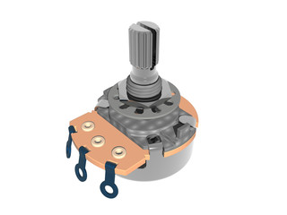
A potentiometer is a three-terminal device that consists of a resistive element, a sliding contact (wiper), and two end terminals. The resistive element can be made of materials such as carbon, wire wound, or conductive plastic, and its resistance is proportional to its length. The sliding contact is connected to a mechanical knob or lever that can be rotated or moved along the resistive element, allowing users to change the amount of resistance in the circuit.
How to Use a Potentiometer
Using a potentiometer is easy and straightforward. Here are the steps:
- Identify the terminals: Most potentiometers have three terminals – two outer terminals and one central terminal. The external terminals are connected to the ends of the resistive element, while the central terminal is connected to the sliding contact.
- Connect the potentiometer to the circuit: Connect one of the outer terminals to the positive terminal of the power supply, the other outer terminal to the negative terminal of the power supply, and the central terminal to the input or output of the circuit. The exact connection will depend on the type of circuit and the intended use of the potentiometer.
- Adjust the potentiometer: Use the knob or lever to adjust the amount of resistance in the circuit. Turning the knob or moving the lever changes the position of the sliding contact along the resistive element, which in turn changes the amount of resistance in the circuit.
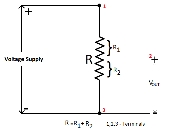
Image Source: circuitstoday.com
Types of Potentiometers
There are several types of potentiometers, including:
- Linear Potentiometers: These have a linear resistance taper, which means that the resistance changes linearly as the knob or lever is moved.
- Logarithmic Potentiometers: Also known as audio taper potentiometers, these have a logarithmic resistance taper commonly used in audio equipment to provide smooth volume control.
- Digital Potentiometers: These are potentiometers that use digital signals to control the resistance instead of a mechanical knob or lever. They are commonly used in digital circuits and microcontrollers.
Conclusion
Potentiometers are versatile components that can be used to adjust the amount of resistance in a circuit. Following the simple steps outlined in this article, you can easily use potentiometers in your circuits. With the various types available, you can choose the one that best suits your needs and intended application.
If you want to try the effect of potentiometer yourself, you can refer to the link below.
English Version
Potentiometers, also known as pots, are variable resistors that allow users to adjust the amount of resistance in a circuit. They are commonly used in electronic devices such as audio equipment, lighting systems, and motor controllers. In this article, we will introduce the basics of potentiometers and provide a step-by-step guide on how to use them in your circuits.
What is a Potentiometer?
A potentiometer is a three-terminal device that consists of a resistive element, a sliding contact (wiper), and two end terminals. The resistive element can be made of materials such as carbon, wire wound, or conductive plastic, and its resistance is proportional to its length. The sliding contact is connected to a mechanical knob or lever that can be rotated or moved along the resistive element, allowing users to change the amount of resistance in the circuit.
How to Use a Potentiometer
Using a potentiometer is easy and straightforward. Here are the steps:
- Identify the terminals: Most potentiometers have three terminals – two outer terminals and one central terminal. The external terminals are connected to the ends of the resistive element, while the central terminal is connected to the sliding contact.
- Connect the potentiometer to the circuit: Connect one of the outer terminals to the positive terminal of the power supply, the other outer terminal to the negative terminal of the power supply, and the central terminal to the input or output of the circuit. The exact connection will depend on the type of circuit and the intended use of the potentiometer.
- Adjust the potentiometer: Use the knob or lever to adjust the amount of resistance in the circuit. Turning the knob or moving the lever changes the position of the sliding contact along the resistive element, which in turn changes the amount of resistance in the circuit.
Image Source: circuitstoday.com
Types of Potentiometers
There are several types of potentiometers, including:
- Linear Potentiometers: These have a linear resistance taper, which means that the resistance changes linearly as the knob or lever is moved.
- Logarithmic Potentiometers: Also known as audio taper potentiometers, these have a logarithmic resistance taper commonly used in audio equipment to provide smooth volume control.
- Digital Potentiometers: These are potentiometers that use digital signals to control the resistance instead of a mechanical knob or lever. They are commonly used in digital circuits and microcontrollers.
Conclusion
Potentiometers are versatile components that can be used to adjust the amount of resistance in a circuit. Following the simple steps outlined in this article, you can easily use potentiometers in your circuits. With the various types available, you can choose the one that best suits your needs and intended application.
If you want to try the effect of potentiometer yourself, you can refer to the link below.
日本語版
ポテンショメータ(可変抵抗器)は、回路内の抵抗値をユーザーが調整できる可変抵抗器です。オーディオ機器、照明システム、モーターコントローラーなどの電子機器で広く使用されています。この記事では、ポテンショメータの基礎を紹介し、回路での使い方をステップバイステップで解説します。
ポテンショメータとは?
ポテンショメータは、抵抗素子、摺動接点(ワイパー)、および2つの端子で構成される3端子デバイスです。抵抗素子はカーボン、巻線、導電性プラスチックなどの材料で作られ、その抵抗値は長さに比例します。摺動接点は機械式のノブまたはレバーに接続されており、抵抗素子に沿って回転または移動させることで、回路内の抵抗値を変更できます。
ポテンショメータの使い方
ポテンショメータの使用は簡単です。手順は以下の通りです:
- 端子を確認する:ほとんどのポテンショメータには3つの端子があります。2つの外側端子と1つの中央端子です。外側端子は抵抗素子の両端に接続されており、中央端子は摺動接点に接続されています。
- ポテンショメータを回路に接続する:外側端子の一方を電源のプラス端子に、もう一方の外側端子を電源のマイナス端子に、中央端子を回路の入力または出力に接続します。正確な接続方法は、回路の種類とポテンショメータの使用目的によって異なります。
- ポテンショメータを調整する:ノブまたはレバーを使って回路内の抵抗値を調整します。ノブを回したりレバーを動かしたりすると、抵抗素子に沿った摺動接点の位置が変わり、それによって回路内の抵抗値が変化します。
画像出典: circuitstoday.com
ポテンショメータの種類
ポテンショメータにはいくつかの種類があります:
- リニアポテンショメータ:リニア抵抗テーパーを持ち、ノブやレバーの移動に伴って抵抗値が直線的に変化します。
- 対数ポテンショメータ:オーディオテーパーポテンショメータとも呼ばれ、対数抵抗テーパーを持ち、オーディオ機器でスムーズな音量制御を提供するために一般的に使用されます。
- デジタルポテンショメータ:機械式のノブやレバーの代わりにデジタル信号を使用して抵抗を制御するポテンショメータです。デジタル回路やマイクロコントローラーで一般的に使用されます。
まとめ
ポテンショメータは、回路内の抵抗値を調整できる汎用性の高いコンポーネントです。この記事で説明した簡単な手順に従えば、回路でポテンショメータを簡単に使用できます。さまざまな種類が利用可能なので、ニーズや使用目的に最も適したものを選択できます。
ポテンショメータの効果を自分で試してみたい方は、以下のリンクを参照してください。